A) 40 kHz
B) 20 kHz
C) 0 Hz
D) unknown
Correct Answer

verified
Correct Answer
verified
Multiple Choice
If a load is purely inductive and the reactive power is 10 VAR, the apparent power is ________.
A) 14.14V
B) 3.16V
C) 10V
D) 1.144V
Correct Answer

verified
Correct Answer
verified
True/False
Power dissipated by the resistor in a parallel RL circuit can be increased With the addition of a capacitor in parallel.
Correct Answer

verified
Correct Answer
verified
True/False
An ohmmeter can be used to accurately test the impedance of an RL circuit.
Correct Answer

verified
Correct Answer
verified
Multiple Choice
If the true power is 10W and the reactive power is 10 VAR, the apparent power is ________.
A) 5V
B) 14.1V
C) 20V
D) 100V
Correct Answer

verified
Correct Answer
verified
True/False
The impedance of a series RL circuit is found by adding the values of XL and R using a phasor diagram.
Correct Answer

verified
Correct Answer
verified
Multiple Choice
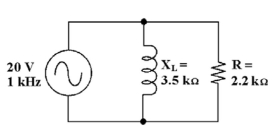
 -What change Would increase the power factor in Figure 12-2?
A) increasing the value of the resistor
B) decreasing the source voltage
C) decreasing the value of the resistor
D) increasing the source voltage
Correct Answer

verified
Correct Answer
verified
Multiple Choice
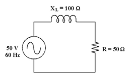
 -If the frequency increases in Figure 12-1, inductance ________.
A) increases
B) decreases
C) decreases to zero
D) remains the same
Correct Answer

verified
Correct Answer
verified
Multiple Choice
In an RL filter circuit, the cutoff frequency is defined as the frequency at Which:
A) the outputVoltage drops to 33% of maximum.
B) the outputVoltage drops to 70% of maximum.
C) the outputVoltage is cutoff, with minimum or zero output.
D) the outputVoltage drops to 66% of maximum.
Correct Answer

verified
B
Correct Answer
verified
Multiple Choice
 -If the frequency increases in Figure 12-1, the phase angle ________ and the impedance ________.
A) decreases, decreases
B) decreases, increases
C) increases, decreases
D) increases, increases
Correct Answer

verified
D
Correct Answer
verified
Multiple Choice
 -What is the cut off frequency in Figure 12-1?
A) 63 Hz
B) 30 Hz
C) 25 Hz
D) 408 Hz
Correct Answer

verified
A
Correct Answer
verified
Multiple Choice
In a series RL circuit, as the phase angle between the applied voltage and the total current increases, this is the same as:
A) power factor increasing.
B) true power decreasing.
C) power factor decreasing.
D) apparent power decreasing.
Correct Answer

verified
Correct Answer
verified
Multiple Choice
 -What is the total impedance in Figure 12-2?
A) 5.71
B) 9.09
C) 1.07
D) 1.86
Correct Answer

verified
Correct Answer
verified
Multiple Choice
If a high-pass RL filterʹs cutoff frequency is 55 kHz, its bandwidth is theoretically ________.
A) 0 kHz
B) 55 kHz
C) 110 kHz
D) infinite
Correct Answer

verified
Correct Answer
verified
True/False
The overall phase angle of a parallel circuit with a resistance of 20 and an inductive reactance of 25 would be nearly 90 degrees.
Correct Answer

verified
Correct Answer
verified
Multiple Choice
 -If the resistor decreases in Figure 12-2, the total current ________.
A) remains the same
B) decreases
C) increases
D) decreases to zero
Correct Answer

verified
Correct Answer
verified
True/False
The source voltage always leads the total current in an RL circuit.
Correct Answer

verified
Correct Answer
verified
Multiple Choice
 -If the resistance increases in Figure 12-2, the total current ________.
A) decreases
B) decreases to zero
C) remains the same
D) increases
Correct Answer

verified
Correct Answer
verified
Multiple Choice
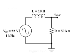
 -The circuit in Figure 12-3 is known as a ________ filter.
A) band-pass
B) low-pass
C) high-pass
D) notch
Correct Answer

verified
Correct Answer
verified
Multiple Choice
 -If the operating frequency decreases in Figure 12-1, the current ________.
A) decreases
B) increases
C) decreases to zero
D) remains the same
Correct Answer

verified
Correct Answer
verified
Showing 1 - 20 of 64
Related Exams